Screwdriver Ring
For this project, my teammate and I designed and manufactured a wearable injection-molded ring with a functional screwdriver bit. The primary design requirements were as follows:
-
The final design should be primarily composed of injection-molded plastic.
-
The product consists of two components, with at least one injection-molded, joined with an appropriate plastic joining method (ex. over-molding, snap fits, etc.)
-
The design must be injection-molded using a mold consisting of two 2” x 4” x 6” aluminum blocks.
Additionally, we self-imposed the requirements of designing a ring that is comfortable to wear, and making sure the screwdriver bit is reasonably functional.
Results
Overall, our final product turned out very well. The ring is made with glow-in-the-dark polyethylene plastic over-molded onto a COTS Phillips screwdriver bit. We produced seven of these rings, and three of those had no manufacturing issues.


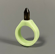
The main principles of the brand we designed our ring for were 1) convenience, 2) comfort, and 3) functionality. The driving inspiration of the entire design is convenience, as we conceptualized the ring as a tool one could easily take with them. To ensure comfort, since we could not have any flat faces on our ring to meet draft angle requirements, we designed our ring with smooth curves on every face and fillets on every corner, which required an extra step of 3D machining. The thickness of the ring was limited by our tooling options (the smallest cutting tool at our disposal was a 1/16” ball end mill), and as a result the final product ended up quite a bit thicker than most commercial rings, but we kept the thickness as small as possible and 3D printed iteration of our ring throughout the design process to make sure it was reasonably comfortable. In the end, we found that the larger thickness actually significantly increased the structural integrity of the ring.
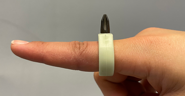
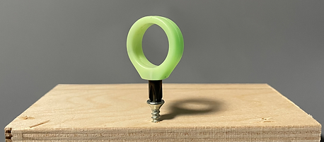
Finally, for ensuring functionality, we had a minor dilemma when deciding what kind of plastic we wanted to use. We primarily considered black ABS and glow-in-the-dark PE (polyethylene). The ABS would have had a higher tensile strength, which is important for a product that would undergo high forces as a tool, but we strongly felt that using glow-in-the-dark plastic would increase the convenience and functionality of the design as something that could be easily found. Therefore, we used the glow-in-the-dark PE. The first few rings that we manufactured were made with ABS, and we found no significant difference in the experience of using those compared to the PE rings.
Skills Developed
Over the course of this project, I developed/learned several skills:
1) Mold design: In particular, molds for injection molding. I became familiar with the specific features necessary for ensuring successful pulls of plastic, including runners, gates, cold slug wells, and air vents.

Final Mold with Injection Molding Features
2) 3D CAM: We used 3D CAM tools to achieve smooth curves on our ring profile. This involved becoming familiar with the settings of the CAM software, and gaining an intuition for parameter thresholds that would allow us to get smooth curves with reasonable machining times.
3) CNC machining: Because we used 3D CAM, we made sure to be extra careful while machining our molds, and I further developed my familiarity with CNC machining.
4) Designing for injection molding: Using tools such as flow simulations, I learned how to design for successful and consistent injection molding. I found the most important factors to be the quantity of plastic, orientation of the design, and the location and number of air vents.
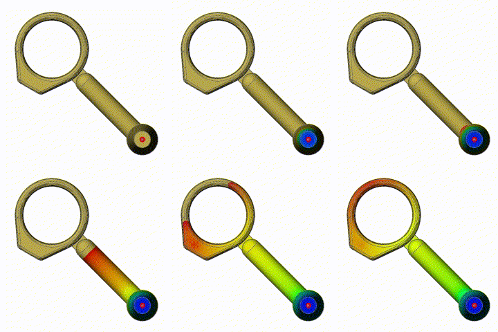
Flow Simulation
Primary Challenges
1) While initially designing the ring, my teammate and I did not consider the available tooling that we could use to machine our molds. This was especially critical for our design since, as it was a ring, we did not want to make the band any thicker than necessary. Additionally, because of the complicated curved profiles on every face of the ring, the thickness of the band was not simply limited to the size of the smallest tool; we needed to leave space for the tool to move around the contours of the ring. Because of this, there was no simple way to figure out the minimum thickness of the ring. Instead, we had to play around with the settings of the CAM and use the machining simulations to observe when all the material of the mold was being machined properly.
2) Having had no experience with injection molding before, our team had to consult a lot of resources to make the overmolding process go well. The main challenges were making sure the screwdriver bit would be properly held by the ring, and figuring out how to fixture the bit in the mold before injection molding. To address the first issue, we used the geometry of our COTS screwdriver bits to our advantage. The cross-section of the bits changed from a smaller circular area to a slightly larger hexagonal profile, and the only part that stuck out from the ring had the round cross-section. When we cut the bits down to fit in the ring, we left part of the hexagonal shaft so that plastic would mold around the entire larger shaft. As a result, the only way the bit can get pulled out of the ring is if the plastic breaks.

Cross-section of bit within ring, showing contained larger cross-section
Fixturing the bit took a little more work. We decided to machine a channel into the mold for the round shaft of the bit to sit in, but we were unsure how to tolerance the channel to get a press-fit. We did not want to risk making the channel too large and allowing plastic to flow into it and around the bit. When we initially machined the mold, we discovered that the channel was too small for the bits. We found that the easiest solution was to keep the molds fixtured in the CNC mill and slowly widen the channel at about .001” at a time, checking the fit each time until the bit fit properly.
3) We found the process of injection-molding the rings to be rather finicky, and encountered a few problems along the way. In our initial tests with black ABS, we kept getting pronounced knit lines in our rings. Increasing the amount of time injection only resulted in flashing without solving the issue. Luckily, when we switched to the glow-in-the-dark PE, the knit lines practically disappeared, but we did have other issues instead. Some of the rings would get hollows by the gate, even when the entire rest of the ring was filled and had started to cause flashing. While post-processing and removing the gates, we found that some of the hollows were deep enough that the rings would have holes through the entire band. We were not entirely sure how to deal with this issue; possible solutions could be changing the temperature of the plastic or increasing the injection force.


Rings before post-processing
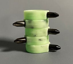

We also had issues fully purging the injection-molding machine of the previously-used black ABS, and several of the rings ended up with black streaks throughout; however, since this was purely an aesthetic issue, and did not affect the glow, we decided we didn’t mind the look of the streaks.
Final rings, some with black streaks
Additional Materials
Because of the nature of injection molding, the cost of the mold is much higher than the cost of the injection molding materials. As a process meant for part volumes on the scale of thousands, the cost per unit drastically decreases as the number of units produced increases. For manufacturing our ring, the cost of producing one ring is 113 times the cost per ring if producing a thousand.


Below is our bill of materials, as well as an ideal-case cycle time breakdown.
Bill of Materials

Cycle Time Breakdown