Ergonomic Steering Wheel Research
Formula SAE, Cockpit Subteam
In my second semester as a cockpit subteam member of Olin Electric Motorsports, our Formula SAE team, I conducted research into ergonomic steering wheel design with another subteam member. Our research was not meant for immediate integration with the cockpit; instead, it is meant to be a reference for future iterations of the vehicle. Our aim was to research more ergonomic design options for the Formula vehicle steering wheel. The images below show the current steering wheel at the time we conducted our research.


The following were our constraints based on official rules and design requirements:
-
Oval/circular shape (continuous perimeter required)
-
Cannot be higher than front roll hoop
-
Largest diameter approx. 10.5in (subject to change)
-
To avoid hitting legs when turning
-
-
Smallest diameter approx. 6in (subject to change)
-
Room needed for LEDs, steering shaft mount, finger space, etc.
-
Our first step was to ideate and analyze some options for the basic structure of the wheel, as seen below.


Pros:
-
More hand/finger space
-
Potentially more room for PCB and mount
Cons:
-
Possibly less structural integrity
-
Hands might slide when turning wheel
Pros:
-
Contour potentially “fits” average hands size better
-
Less squished fingers
Cons:
-
Less finger room
-
Might be harder to hold for smaller hands
Pros:
-
Worked as a previous design
-
Proven to be structurally sound
Cons:
-
Finger orientation may be less natural
-
Less room for electrical parts
Based on our analysis and consultation with senior members of the team, we decided to proceed with the third design (leftmost). Our next step was to create a model of our steering wheel. We decided to use clay for this so that we could ask potential drivers to try gripping the wheel. We could then mimic the contours formed by their hands in our design. Below is one of our clay models; we used the models to experiment with the dimensions of the spaces in the sides of the wheel.
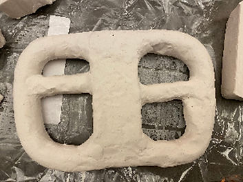
One notable change we made after constructing the clay model is that we decided to replace the hollow area in the middle of the wheel, which previously house electrical components, with a flat plate. This change would allow our wheel to be much thinner in the middle than before, which meant a reduction in weight.
Our final step was to create a 3D model in SolidWorks. This required a lot of research into making contours within SolidWorks, which was something neither myself nor my partner had much previous experience in. Our 3D model can be seen below. The model consists of a flat plate in the middle with contoured handler. The positioning of the contours was based on our user-testing with the clay model. The model has an extruded cut on the back of the wheel where the quick release mount sits. The box on the back of the wheel is for the button wire. The final diameter of the model was 9.8 in, which was within our constraints.


Out of curiosity, nearing the end of the semester, my partner and I also did some introductory research into composite fabrication. One of the issues with the current wheel design was that it was somewhat difficult for the driver to grip while wearing bulky gloves, and we considered that a potential solution to this problem could be 3D printing the flat plate with a skeleton of the handles, and then casting the contoured handles in silicon urethane or foam.